
High Frequency
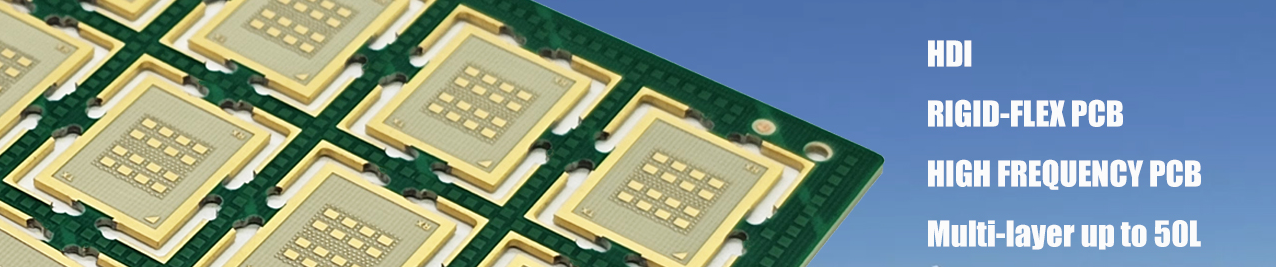
HIGH FREQUENCY PCB Materials for frequencies up to 100GHz, cavities etc. High frequency PCBs can be single-sided, double-sided or multilayer structures. Special materials are required to achieve the high frequency provided by this type of printed circuit board - any changes in the Er value of these materials can affect the impedance of the board. Many PCB designers turn to Rogers dielectric material for its lower dielectric loss, reduced signal loss, lower cost of circuit fabrication and better suitability for fast-turnaround prototyping applications. They have a smaller and stable Dielectric Constant (Dk) (ranges from 2.1 to 5) to prevent delay in signal transmission. The lower the Dk value, the higher the frequency transmission rate. The dissipation factor (DF) is small to avoid affecting the signal transmission rate. Therefore, try to work with a DF of between 0.0019 and 0.025 for quality signal transmission. The boards ensure the thermal expansion rate of the laminates is the same as that of the copper foil. This will prevent the separation of copper foil when there is a temperature variation. High-frequency PCBs ensure appropriate thermal resistance, impact endurance, chemical resistance, and peel-off resistance. Typical applications in today’s world are base stations, radar and global positioning systems (GPS). 5G technology and the IOT also use this type of PCB.
HIGH FREQUENCY PCB
Parameter
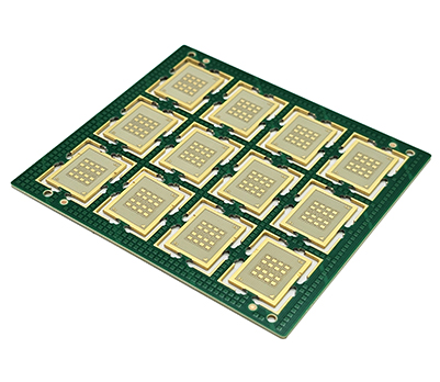
Product Type: Rigid PCB Layer count: 8 Board thickenss: 0.8mm copper thickness: 1/0.5/0.5/0.5/0.5/1oz Speciality: Anylayer M7 ENEPIG8u"+Selective gold plating30u" Metalized edge
Applications
Data & Communication